Configure Aruba VSX on 8100 series
There are a few steps that need to be performed, as outlined:
- disable Aruba Central (if device is connected to it)
- configure LAG (link aggregation)
- assign interfaces to the LAG
- check status of the LAG to confirm its operation
- configure/form the VSX cluster
- check status of VSX cluster
- configure keepalive link
- check status of the cluster
The keepalive link in an Aruba VSX cluster plays a vital role in keeping the network running smoothly. Acting as a heartbeat between the two switches, it constantly checks the status and health of each one to make sure they're in sync and communicating properly. If one switch goes down, the keepalive link quickly detects the problem and triggers an immediate failover to the other switch, preventing any network downtime. Moreover, the keepalive link helps avoid a split-brain scenario, where both switches could mistakenly try to act as the active switch, causing network conflicts and data issues. By ensuring only one switch is active at a time and enabling quick failover, the keepalive link boosts the resilience and reliability of your VSX cluster, ensuring that the network stays up and running without issues.
Let's start by disabling access to Aruba Central first:
# configure
(config)# aruba-central
(config-aruba-central)# disable
(config-aruba-central)# end
Next, we will configure the LAG interface:
(config)# interface lag XYZ
(config-lag-if)# no shutdown
(config-lag-if)# description VSX-LAG
(config-lag-if)# no routing
(config-lag-if)# vlan trunk native 1 tag
(config-lag-if)# vlan trunk allowed all
(config-lag-if)# lacp mode active
(config-lag-if)# exit
In this configuration we are assigning a description to the interface (VSX-LAG in this example), disabling routing on it, setting native VLAN to 1 (this may be different for your environment) and allowing all VLANs to pass through the trunk between them. We are also setting LACP to active mode. Repeat this operation on both switches in the stack.
Next, we will assign physical interfaces to this newly created LAG interface:
(config)# interface 1/1/X-1/1/Y
(config-if-<1/1/X-1/1/Y>)# no shutdown
(config-if-<1/1/X-1/1/Y>)# lag XYZ
(config-if-<1/1/X-1/1/Y>)# exit
Once this operation is completed on both switches, we can check status of the LAG:
# sh lag XYZ
System-ID       : XY:XY:XY:XY:XY:XY
System-priority : 65534

Aggregate lagXYZ is up
 Admin state is up
 Description : VSX-LAG
 Type                        : normal
 Lacp Fallback               : Disabled
 MAC Address                 : XY:XY:XY:XY:XY:XY
 Aggregated-interfaces       : 1/1/X 1/1/Y
 Aggregation-key             : 256
 Aggregate mode              : active
 Hash                        : l3-src-dst
 LACP rate                   : slow
 Speed                       : 200000 Mb/s
 Mode                        : trunk
If everything looks OK, we can continue with configuring the VSX:
(config)# vsx
(config-vsx)# inter-switch-link lag XYZ
(config-vsx)# role primary
(config-vsx)# linkup-delay-timer 30
(config-vsx)# exit
Repeat the commands on the second switch and once completed, we can check the status of the cluster:
# sh vsx status
VSX Operational State
---------------------
  ISL channel             : In-Sync
  ISL mgmt channel        : operational
  Config Sync Status      : In-Sync
  NAE                     : peer_reachable
  HTTPS Server            : peer_reachable

Attribute           Local               Peer
------------        --------            --------
ISL link            lagXYZ              lagXYZ
ISL version         2                   2
System MAC          XY:XY:XY:XY:XY:XY   XY:XY:XY:XY:XY:XY
Platform            8100                8100
Software Version    LL.10.13.1010       LL.10.13.1010
Device Role         primary             secondary
If all looks good, we can configure keepalive link next. As explained, keepalive links will make sure that there are no issues with the switches operation, and to do that, we will use a dedicated interface for keepalive. Since these will be configured as routed ports, we will dedicate a new, non-routed subnet, to this link:
(config)# vrf KEEPALIVE
(config-vrf)# exit
(config)# interface 1/1/X
(config-if)# no shutdown
(config-if)# vrf attach KEEPALIVE
(config-if)# description VSX-KeepAlive-Link
(config-if)# ip address 192.168.254.1/24
(config-if)# exit
Repeat the commands on the second switch and just remember to assign a different IP address to the second switch's link (192.168.254.2/24).
Finally, let's add the keepalive config to the VSX config:
(config)# vsx
(config-vsx)# keepalive peer 192.168.254.2 source 192.168.254.1 vrf KEEPALIVE
(config-vsx)# end
# wr mem
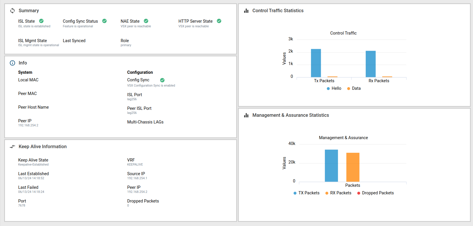
Repeat the commands and modify the peer and source IPs as per your IP scheme. If everything worked out, you can check the status in the GUI as well:

And that's it - if everything went well, you should now have a fully functional VSX cluster!
Member discussion